



Aluminum Reducer — Concentric & Eccentric Butt-Weld Reducers
Customer service is online. Enter the chat to get the latest quotation.
 Spot stock
 Customize
 Factory direct sale
 7 days delivery
What an Aluminum Reducer Does
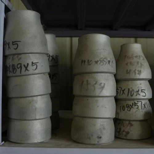
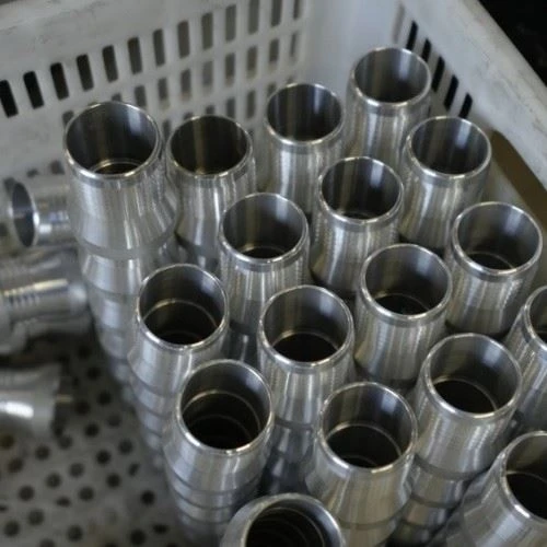
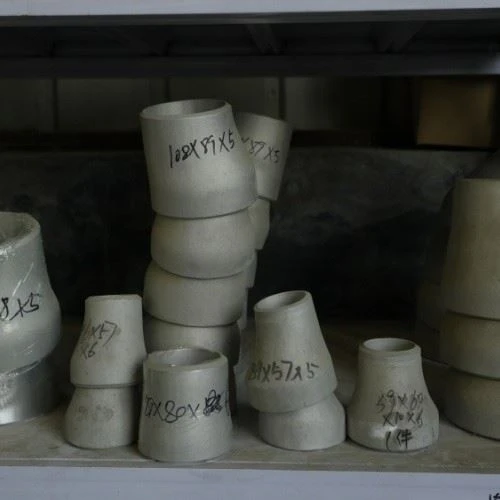
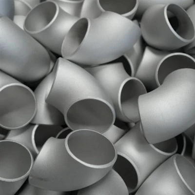
An aluminum reducer connects two pipes of different diameters on the same line. In aluminum pipe systems you meet it wherever the line changes size: dropping from a main header to a smaller branch, transitioning between a feed pump and a distribution header, or stepping down to an instrument tap.
Two geometries cover almost every case:
Aluminum Concentric reducer - both end centerlines sit on the same axis. The default choice for vertical lines and for single-phase flows where no gas or liquid can get trapped.
Aluminum Eccentric reducer - one end offsets so the top or the bottom of the two ends stays flat. Top-flat keeps gas pockets out of horizontal lines; bottom-flat keeps liquid from pooling and lets the line drain.


Specifications of Aluminum Reducer
|
Item |
Options |
|
Type |
Concentric, eccentric (top-flat or bottom-flat) |
|
Connection |
Butt-weld (BW); socket-weld (SW, class 3000) and threaded (NPT/BSP) in small sizes |
|
Manufacturing |
Seamless extruded (≤ 12" run), fabricated/formed and welded (≥ 8" run), forged (small SW/threaded) |
|
Size range |
¾" × ½" NPS – 24" × 20" NPS (DN20×DN15 – DN600×DN500). Larger on RFQ. |
|
Reduction step |
Single-step (e.g., 4" × 2") or two-step step-down (e.g., 6" × 4" × 2", custom) |
|
Wall thickness |
SCH 40 / SCH 80 stock; SCH 5S/10S/40S/80S, SCH 160, XXS on request - same schedule as the run pipe |
|
Alloys |
6061-T6, 6063-T5/T6, 6082-T6, 5083-O, 5086-O, 5052-O, 1100-H14, etc. |
|
Standards |
ASTM B361, ASME SB361, ASME B16.9, ASME B16.52 (forged SW/threaded), EN 755-1 to -9 |
|
Temper |
O / H111 / H112 / T6 / T651 |
|
Surface |
Mill Finish (default), Anodized (type Ii/iii), Brushed, Polished, Painted,Sandblasted |
|
Pressure class |
Per ASME B31.3 allowable-stress tables for the alloy and service temperature |
|
Documentation |
EN 10204 3.1 mill cert, PMI report, dimensional report, hydrostatic test on request |
|
Lead time |
15–25 working days for stock sizes; 30–45 days for custom |
|
Packaging |
VCI film + ISPM 15 wooden case for export; FOB / CIF / EXW / DDP |

Common Alloys of Aluminum Reducer
Most aluminum reducers ship as 6061-T6 (the default for industrial systems) or 5083-O (seawater and cryogenic). Match the reducer to the rest of the line - mixing alloys in one system is possible but rarely worth the galvanic complications.
|
Alloy |
When it earns its place |
|
6061-T6 |
General industrial, hydraulics, compressed air, atmospheric exposure, equipment manifolds |
|
5083-O |
Seawater, brine, chloride exposure, cryogenic service to -196°C, LNG |
|
6063-T6 |
Architectural and decorative pipework, instrument air, visible lines with anodized finish |
|
6082-T6 |
European market equivalent of 6061 with slightly higher strength; common in EU projects |
|
5052-O |
Low-pressure chemical and tank service, light forming |
|
1100-H14 |
Low-pressure utility lines and chemical tanks where cost matters most |
Note on tempers: 6063-T5 means the extrusion is cooled from the press and aged directly, without a separate solution heat treatment - slightly lower strength than T6, fine for non-pressure architectural work. We stock both.
Chemical composition (per ASTM B221 / B209, wt%, Al balance):
|
Element |
6061 |
6063 |
6082 |
5083 |
5086 |
5052 |
|
Si |
0.40–0.80 |
0.20–0.60 |
0.70–1.30 |
≤0.40 |
≤0.40 |
≤0.25 |
|
Fe |
≤0.70 |
≤0.35 |
≤0.50 |
≤0.40 |
≤0.50 |
≤0.40 |
|
Cu |
0.15–0.40 |
≤0.10 |
≤0.10 |
≤0.10 |
≤0.10 |
≤0.10 |
|
Mn |
≤0.15 |
≤0.10 |
0.40–1.00 |
0.40–1.00 |
0.20–0.70 |
≤0.10 |
|
Mg |
0.80–1.20 |
0.45–0.90 |
0.60–1.20 |
4.00–4.90 |
3.50–4.50 |
2.20–2.80 |
|
Cr |
0.04–0.35 |
≤0.10 |
≤0.25 |
0.05–0.25 |
0.05–0.25 |
0.15–0.35 |
|
Zn |
≤0.25 |
≤0.10 |
≤0.20 |
≤0.25 |
≤0.25 |
≤0.10 |
Mechanical properties - ASTM B221 specification minimums and typical values, separate columns on purpose:
|
Alloy · Temper |
Tensile min/typ (MPa) |
Yield min/typ (MPa) |
Elongation min |
|
6061-T6 |
290 / 310 |
241 / 276 |
10% (8% if wall ≤1/16") |
|
6063-T5 |
186 / 205 |
145 / 170 |
8% |
|
6063-T6 |
207 / 240 |
172 / 214 |
8% |
|
6082-T6 |
310 / 330 |
260 / 300 |
10% |
|
5083-O |
269 / 290 |
110 / 145 |
16–20% (by thickness) |
|
5083-H116 |
303 / 315 |
228 / 240 |
10% |
|
5086-O |
241 / 260 |
96 / 115 |
16% |
|
5052-O |
172 / 190 |
65 / 90 |
14% |
|
1100-H14 |
110 / 125 |
95 / 110 |
8% |
Welded vs seamless
- Seamless extruded (run ≤ 12"): the taper is formed from a seamless extrusion, no longitudinal weld to inspect. Higher pressure rating for the same wall.
- Fabricated welded (run ≥ 8", common at 14" and above): formed from plate, rolled and welded. If your design uses a joint efficiency of 1.0, ASME B31.3 requires 100% radiographic or equivalent NDT on the longitudinal seam; if the seam is derated (E < 1.0), the NDT scope is reduced accordingly. We can document either route - tell us which one your project runs.
For pressure-service orders, ask for the WPS and PQR at the inquiry stage.
Standards of Aluminum Reducer
|
Standard |
What it covers |
|
ASTM B361 |
Factory-made wrought aluminum welding fittings - material standard |
|
ASME SB361 |
ASME material version of B361 |
|
ASME B16.9 |
Dimensions and tolerances for wrought butt-weld fittings |
|
ASME B16.52 |
Forged aluminum socket-weld and threaded fittings |
|
EN 755-1 to -9 |
Wrought aluminum extrusion products (bar, tube, profile) |
|
EN 10204 3.1 |
Mill test certificate with inspection by the manufacturer |
Sizes and Dimensions
A reducer is specified by the larger (run) NPS first, then the smaller (branch) NPS. Per ASME B16.9, the end-to-end length H depends only on the larger end:
|
Run NPS × Branch NPS |
H (mm) |
|
¾ × ½ |
38 |
|
1 × ¾ |
51 |
|
1¼ × 1 |
51 |
|
1½ × 1 |
64 |
|
2 × 1 |
76 |
|
2 × 1½ |
76 |
|
2½ × 2 |
89 |
|
3 × 2 |
89 |
|
3½ × 3 |
102 |
|
4 × 3 |
102 |
|
5 × 4 |
127 |
|
6 × 4 |
140 |
|
8 × 6 |
152 |
|
10 × 8 |
178 |
|
12 × 10 |
203 |
|
14 × 12 |
330 |
|
16 × 12 |
356 |
|
18 × 16 |
381 |
|
20 × 16 |
508 |
|
22 × 20 |
508 |
|
24 × 20 |
508 |
Eccentric reducers share the same length; only the small-end offset direction changes. Note the jump in H above 14" run - that is the standard table, not a typo.
Tolerances (per ASME B16.9):
|
Item |
Tolerance |
|
Length H, run NPS ≤ 24" |
±2 mm (we hold this band even where the standard allows wider) |
|
Length H, run NPS 26–48" |
±5 mm |
|
End alignment (eccentric offset), ≤ 8" |
±1 mm |
|
End alignment, 10–24" |
±2 mm |
|
Wall thickness |
not less than 87.5% of nominal |
|
Outside diameter at bevel, ≤ 24" |
+1.6 / -0.8 mm |
Two-step "step reducers" (e.g., 6" × 4" × 2" in one piece) are custom fabrications, not a B16.9 standard item. We build them as a single welded assembly to your overall-length requirement - typically 10" long for the 6×4×2 example. Say so in the inquiry.
Manufacturing Process of Aluminum Reducer
By size:
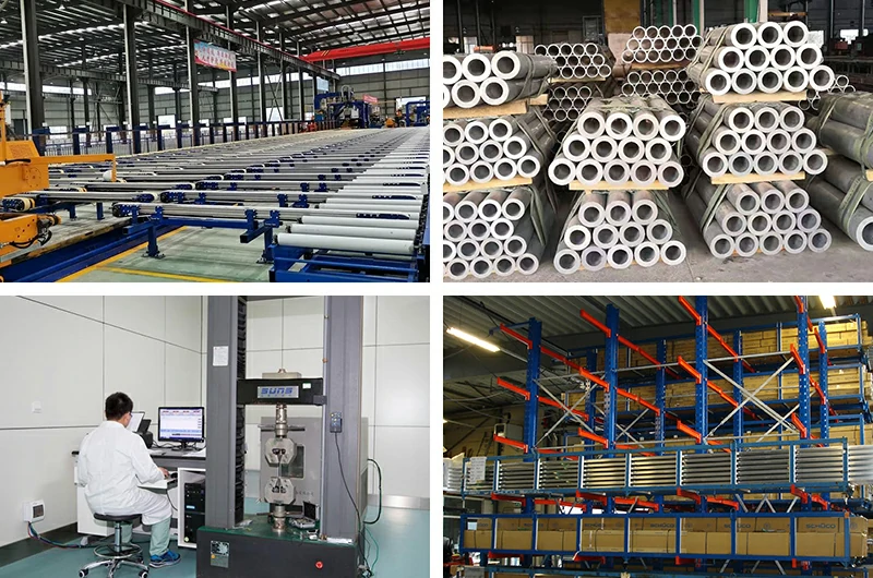
¾" through 6" run - extruded pipe section, hot-formed to the taper, ends machined. No internal weld.
8" through 16" run - formed from plate, two halves rolled and welded longitudinally, ends machined. Full-penetration TIG seam; 100% visual + dye-penetrant on every weld as standard.
18" run and above - heavy-plate fabrication with segmented welds. Full WPS/PQR package available on request.


Quality Inspection
Material verification - PMI per heat before forming.
Dimensional - length H, eccentric offset, end bores, wall thickness at both ends.
Visual + NDT - full visual; dye-penetrant or radiography on welds for pressure-rated orders.
Hydrostatic test - 1.5 × design pressure at ambient, held 5 minutes as our shop standard (10 minutes if your spec asks; B31.3 leaves the hold time to the engineer).
Documentation - EN 10204 3.1, PMI, weld inspection, dimensional report.
Marking per piece: manufacturer, alloy, run × branch NPS, schedule, heat number, standard.
Applications of Aluminum Reducer Tube Pipe
Hydraulic systems - return-line headers stepping down to smaller distribution. Concentric on vertical drops; eccentric top-flat on horizontal returns to stop air pockets.
Compressed air - main header to branch lines. Eccentric top-flat is the standard call, so condensate cannot sit at the low point.
Chemical process lines - vessel-to-instrumentation step-downs. Concentric unless the flow is two-phase gas-liquid; then eccentric.
Marine / seawater - 5083-O for ballast, bilge and seawater cooling lines. Say 5083 on the PO; 6061 in continuous seawater will pit within months.
Cryogenic / LNG - 5083-O, rated to -196°C. Eccentric top-flat on horizontal LNG vapor lines keeps the gas-liquid interface uniform.
Architectural - visible drops, atrium piping, decorative headers. 6063-T6 with Type II anodized colour match.
Equipment OEM - pump suction reducers must be eccentric, flat side up, to keep vapor out of the pump eye (API 610 requirement, not a preference). Pump discharge reducers are normally concentric. Get this one backwards and you buy a cavitated pump.


Concentric vs eccentric - selection matrix (general piping engineering practice; applies to any material):
|
Service |
Concentric |
Eccentric top-flat |
Eccentric bottom-flat |
|
Vertical line, single-phase |
✓ Default |
Avoid |
Avoid |
|
Horizontal line, single-phase liquid |
OK |
✓ Default |
OK |
|
Horizontal line, single-phase gas |
OK |
✓ Default |
OK |
|
Horizontal line, two-phase gas-liquid (gas dominant) |
Avoid - air pocket |
✓ Default |
Avoid - liquid pocket |
|
Horizontal line, slurry |
Avoid - settling |
Avoid |
✓ Default |
|
Pump suction |
Avoid - vapor / vortex |
✓ Default (API 610) |
Only if flat side down is engineered |
|
Pump discharge |
✓ Default |
Rarely needed |
Rarely needed |
The one rule worth memorizing: pump suction = eccentric, flat side up. Everything else, your engineer can decide from the flow.
Welding Guide
Reducer-to-pipe welding follows the same logic as tee-to-pipe:
6061-T6: ER4043 for general service; ER5356 if the assembly gets anodized afterwards.
5083-O: ER5183 or ER5356.
6063-T6: ER4043 or ER5356; 5356 preferred before anodizing.
Packaging & Logistics
¾" – 2" run: PE bag, carton, palletized, stretch-wrapped.
3" – 6" run: PE wrap, carton, pallet.
8" – 24" run: each piece wrapped, VCI-lined wooden case (ISPM 15 marked), palletized.
Custom step reducers: crated to length.


Lead times:
Stock concentric or eccentric, common alloys (6061-T6, 5083-O, 6063-T6), SCH 40 / SCH 80: 15–25 working days.
Custom step, custom alloy, custom schedule: 30–45 days.
NACE, hydrostatic witnessing or third-party inspection: add 7 days.
Trade terms: EXW Tianjin, FOB Tianjin / Shanghai / Qingdao, CIF destination port, DDP site. FOB is the most common for our aluminum fittings. Typical MOQ is 100 pieces per size; we do split sizes within one PO if quantities are reasonable.
Comparison with other materials
Weights below are for a 4" × 3" SCH40 reducer and are approximate - actual weights go on the packing list.
|
Property |
Aluminum reducer |
304/316 reducer |
Carbon steel reducer |
|
Weight, 4"×3" SCH40 (per piece) |
≈0.5–0.8 kg |
≈1.6–2.3 kg |
≈1.6–2.3 kg |
|
Corrosion - atmosphere |
Excellent (oxide film) |
Excellent |
Poor without paint |
|
Corrosion - seawater |
5083-O only |
316 acceptable |
Poor |
|
Corrosion - strong caustic |
Poor |
OK |
OK |
|
Cost relative (per piece) |
Reference |
2.5–4× |
0.6–0.9× |
|
Continuous service temperature |
≤150°C (peak 200°C derated) |
≤500°C typical |
≤400°C |
|
Cryogenic service |
Yes, 5083-O to -196°C |
Yes, 304L/316 |
Limited (needs L grades) |
|
Welding complexity |
Moderate (TIG, clean prep) |
Moderate (TIG/MIG) |
Easy (SMAW/GTAW) |
|
Galvanic isolation vs steel pipe |
Yes - dielectric |
Optional |
- |
|
Magnetic |
No |
No (304) / slight (316) |
Yes |
Hot Tags: aluminum reducer — concentric & eccentric butt-weld reducers, China aluminum reducer — concentric & eccentric butt-weld reducers manufacturers
Previous
Aluminum Pipe Tee FittingsYou Might Also Like



Send Inquiry